What Is the Largest Voltage the Battery Can Have Without Breaking the Circuit at the Supports?
Connecting Serial-Parallel Batteries Tutorial
by Lewis Loflin
This is an introduction to how to properly connect batteries and cells in series or parallel for greater voltage or electric current. I'll begin with an explanation of terms, and then examples, then experiments. I will just deal hither with direct electric current (DC) devices only. This page has been updated September 2, 2011.
Terms: a jail cell is an individual electrical device. This can be a flashlight cell such as AAA, AA, C, or D cells, or solar cells or even unmarried thermoelectric prison cell. A battery is a grouping of 2 or more than cells. They are connected in series positive (+) to negative (-) for greater voltage, or in parallel (+ to + and - to -) for greater current capacity.

Examples of various cells and batteries.
An everyday examples of a battery is the 9-volt transistor bombardment, which is six 1.5-volt cells in series. The common auto battery consists of six ii.1-volt pb-acrid cells in serial. With a battery of these types that are sealed the failure of a single cell ruins the whole bombardment.
All batteries consist of individual cells. There are two wide categories of cells:
Primary cells are used once and when discharged are thrown away. Common carbon-zinc and Alkaline are examples of this. There take been attempts to recharge these types of batteries, I wouldn't effort this because they could explode or leak.
Secondary cells can be recharged by applying a slightly college voltage (+ to + and - to - ) to the unit of measurement. While a typical automobile battery fully charged will read a little over 12.half dozen volts, the charging arrangement operates at 13-14 volts. Measuring this voltage while the vehicle is idling is a practiced way to test the charging system.
Examples of these type cells are nickel-cadmium (NiCd), lithium-ion used in many laptop computers, and lead-acid. If these are over charged this tin can damage the cells and could pb to spewing or explosion. Notation that the material in lithium cells is highly reactive to air and water and can cause severe chemical burns. Never attempt to open up a lithium cell and if leaking dispose of quickly. Likewise not nickel and cadmium are both toxic heavy metals dispose of properly.
Power Considerations
The output voltage of any cell be information technology chemic, photovoltaic, or thermal is dependant on the materials that brand up the prison cell. So a carbon-zinc cell will produce 1.five volts regardless of size. It can be a AAA or the size of a tanker truck, it's however ane.5 volts. The size does play into current capacity or the amount of electric current the prison cell tin evangelize.
"The more electrolyte and electrode material there is in the prison cell the greater the capacity of the cell. Thus, a pocket-sized cell has less capacity than a larger cell, given the same chemical science (e.g., element of group i cells), though they develop the same open-excursion voltage." (Wiki) This is also known as ampere-hour (Ah) rating.
For example a 6-volt 4.five Ah battery will produce 4.v-amperes of current for 1 hour or i ampere for 4.5 hours. Well, non really. The last few amps often lead to a lower voltage due to increased internal resistance in the jail cell(s). This is true of either principal or secondary cells. All silicon solar cells produce virtually .5 volts, but the greater the concrete area the greater the current chapters.

A working Example
Pictured in a higher place is a 225 watt solar panel made with lx solar cells producing 30 volts at vii.5 amps. In this case nosotros wired all 60 cells in series (.five volts 10 60) for a panel to be used with a 24-volt charging organization. We could accept wired the same panel for 15-volts for a 12-volt charging system by connecting two groups of 30 cells wired in series, and then connecting the ii groups in parallel producing 15 amps of current at 15 volts.
Note that these panels are designed to charge lead-acid batteries or an inverter to feed power to the power line. Power is a product of voltage times electric current, so i solar jail cell advertised on Ebay is a 3' x 6' poly crystalline solar cell that produces 3.6A or a total of i.8 watts at .v volts.
The cells used in the above panel are 6' x half dozen' and this 30 volt rating is at no load. Batteries be they solar or chemical always have higher open-circuit voltages than they do when being used. When testing any battery practice it under load or with a voltmeter fix for checking batteries. (It places a load on the battery internally.)
Nosotros must consider electric current in regards to what size wire we want to use. Higher current require a larger estimate conductor or wire thus more expensive wire. In general we want to limit the length of the wire in very heavy electric current applications. To produce say 1000 watts from a DC-Ac inverter (12VDC to 120VAC) makes more sense to utilise a 24-volt or 48-volt organization to cut downwards on the wire gauge.

Pictured above are cells in serial. They are connected positive to negative and the voltages add while the current or Ampere-hour ratings stay the same. A battery can have any number of cells in series. Cells in series must be the same blazon and rating. We tin can connect a lower capacity prison cell into the string and go the voltages to add, but lower capacity will apace belch that cell acting as a high resistance to the other cells dropping the output voltage.

Pictured above are the same cells in parallel. The output voltages stay the aforementioned, but the current capacity adds. One can take whatever number of cells in parallel, only be sure they are the same chemical blazon and voltage.

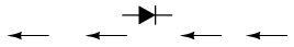
Pictured in a higher place are the symbols for batteries. The one on the right is my symbol for a solar battery or solar panel which includes internal blocking diode, which frequently isn't shown. For the post-obit illustrations I will show the various ways to connect both solar and pb acid cells together. I'll assume the solar cells connected with thirty each in series in two split up panels producing 15 volts at 7.5 amps. I'll as well assume four 6-volt atomic number 82 acid batteries with a electric current rating of 40 Ah.
Note these demand to exist deep-cycle or marine batteries, not everyday car batteries.

Pictured in a higher place is a 24-volt solar charging system. I've wired my 2 12-volt solar panels in serial and the 4 6 volt (really 6.3) volt 40 Ah batteries in series, connected in parallel with the solar panels. This will produce nigh 24 volts at 40 amps for a full power of 960 watts for 1 hour from the four batteries. Or one tin accept 96 watts for ten hours, etc.
We would utilize this to ability a 24-volt inverter that converts DC to 120 volts Air conditioning for powering Ac devices. I model rated at 400 watts is designed for powering solid state items such as computers, radios, etc. A compact fluorescent calorie-free rated at twenty watts would operate for over 48 hours fifty-fifty if no power was being delivered from the solar panels. In daylight power would come from both the batteries and panels. At the full 400 watts in this instance the electric current would be 16.67 amps to the inverter from the bombardment bank.
Diode D1 acts equally an electrical "check valve" allowing current to flow in only one direction. This keeps the batteries from discharging through the solar cells when the output voltage drops below the batteries at dark. The arrow points to the N-blazon semiconductor textile in the diode and is not the management for current catamenia which is from negative to positive. Most websites on solar have this backwards.

Typical ability inverter.
In fact this unabridged organisation be copied then wired in parallel with each other. And then four of these wired in parallel can evangelize 160 amps at 24-volts or 3840 watts for one hour. To me this would be a amend organisation because we would employ smaller judge wire to the batteries and smaller blocking diodes saving money. This would too make each individual department more than repairable without taking the whole arrangement down.

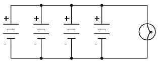
Pictured above is one method to connect our iv 6-volt forty Ah batteries to 2 solar panels connected in parallel. The two panels can deliver a peak current of 15 amps. The capacity of the battery depository financial institution is at present 12-volts at 80 amps. BAT1 and BAT2 are connected in parallel to each other every bit are BAT3 and BAT4 increasing the current rating to fourscore Ah. The two pairs are then continued in serial to produce 12 volts at 80 Ah for a total wattage of 960 watts.
Series batteries
PARTS AND MATERIALS
- Ii vi-volt batteries
- Ane 9-volt battery
Actually, any size batteries will suffice for this experiment, but it is recommended to have at least two different voltages available to make it more interesting.
LEARNING OBJECTIVES
- How to connect batteries to obtain dissimilar voltage levels
SCHEMATIC DIAGRAM
Illustration
INSTRUCTIONS
Connecting components in series means to connect them in-line with each other, so that in that location is only a single path for electrons to flow through them all.
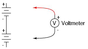
If you connect batteries then that the positive of one connects to the negative of the other, you volition detect that their respective voltages add. Measure out the voltage beyond each battery individually as they are connected, then measure the full voltage beyond them both, similar this:
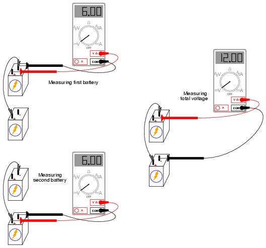
Attempt connecting batteries of different sizes in series with each other, for instance a half-dozen-volt battery with a 9-volt battery. What is the total voltage in this case? Try reversing the terminal connections of just one of these batteries, so that they are opposing each other like this:
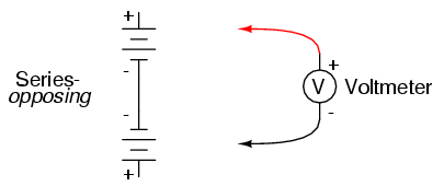
How does the total voltage compare in this situation to the previous one with both batteries "aiding?" Annotation the polarity of the total voltage as indicated by the voltmeter indication and test probe orientation.
Remember, if the meter'south digital indication is a positive number, the red probe is positive (+) and the black probe negative (-); if the indication is a negative number, the polarity is "astern" (reddish=negative, black=positive).
Analog meters simply volition not read properly if opposite-connected, because the needle tries to move the wrong direction (left instead of right). Tin y'all predict what the overall voltage polarity will be, knowing the polarities of the private batteries and their respective strengths?
Parallel batteries
PARTS AND MATERIALS
- Four vi-volt batteries
- 12-volt lite bulb, 25 or l watt
- Lamp socket
Loftier-wattage 12-volt lamps may be purchased from recreational vehicle (RV) and boating supply stores. Common sizes are 25 watt and 50 watt. This lamp will exist used every bit a "heavy" load for your batteries (heavy load = i that draws substantial current).
A regular household (120 volt) lamp socket will work just fine for these low-voltage "RV" lamps.
LEARNING OBJECTIVES
- Voltage source regulation
- Boosting current capacity through parallel connections
Illustration
INSTRUCTIONS
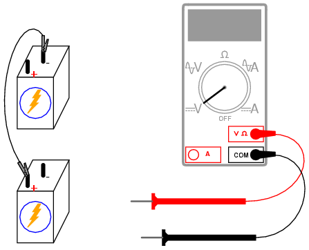
Begin this experiment by connecting 1 half dozen-volt battery to the lamp. The lamp, designed to operate on 12 volts, should glow dimly when powered by the vi-volt battery. Use your voltmeter to read voltage across the lamp similar this:
The voltmeter should register a voltage lower than the usual voltage of the battery. If y'all apply your voltmeter to read the voltage straight at the battery terminals, you volition measure a low voltage at that place as well. Why is this? The big electric current fatigued past the high-power lamp causes the voltage at the battery terminals to "sag" or "droop," due to voltage dropped across resistance internal to the battery.
We may overcome this trouble by connecting batteries in parallel with each other, then that each battery only has to supply a fraction of the total current demanded by the lamp. Parallel connections involve making all the positive (+) battery terminals electrically common to each other by connection through jumper wires, and all negative (-) terminals common to each other as well. Add 1 battery at a time in parallel, noting the lamp voltage with the addition of each new, parallel-connected battery:
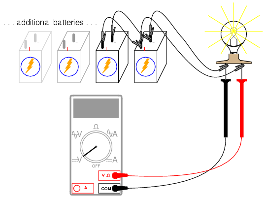
There should too be a noticeable departure in light intensity equally the voltage "sag" is improved.
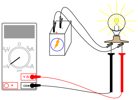
Try measuring the electric current of one battery and comparing it to the total current (calorie-free seedling electric current). Shown here is the easiest way to measure single-battery current:
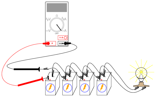
By breaking the excursion for only i battery, and inserting our ammeter within that break, we intercept the current of that one battery and are therefore able to measure out it. Measuring total current involves a similar procedure: make a break somewhere in the path that total current must take, and then insert the ammeter inside than break:
Notation the deviation in current between the unmarried-battery and total measurements.
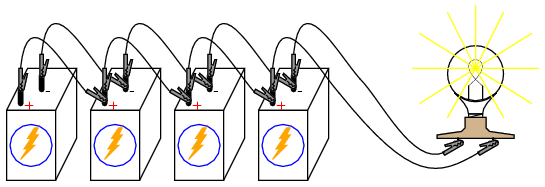
To obtain maximum brightness from the light bulb, a series-parallel connexion is required. Two 6-volt batteries connected series-aiding volition provide 12 volts. Connecting 2 of these series-continued battery pairs in parallel improves their electric current-sourcing ability for minimum voltage sag:

Ref. www.allaboutcircuits.com
- Quick navigation of principal page:
- Bones Electronics Learning and Projects
- Arduino Microcontroller Projects
- Raspberry Pi and Linux
- Connecting a PC Printer Port to Electronics with Python
- Microchip PIC 18F2550
- PICAXE Microcontroller
- New Nov. 2014
- Using the ULN2003A Transistor Array with Arduino YouTube
- ULN2003A Darlington Transistor Assortment with Circuit Examples
- Using the TIP120 & TIP120 Darlington Transistors with Arduino YouTube
- Tutorial Using TIP120 and TIP125 Ability Darlington Transistors
- Driving 2N3055-MJ2955 Power Transistors with Darlington Transistors
- Using Power MOSFETS with Arduino YouTube
- Due north-Channel Power MOSFET Switching Tutorial
- P-Channel Power MOSFET Switch Tutorial
- Using PNP Bipolar Transistors with Arduino, PIC YouTube
- Using NPN Biploar Transistors with Arduino, PIC YouTube
- Understanding Bipolar Transistor Switches
- How to build a Transistor H-Bridge for Arduino, PIC YouTube
- Build a High Power Transistor H-Bridge Motor Control
- Build a Power MOSFET H-Bridge for Arduino, PIC YouTube
- H-Span Motor Command with Ability MOSFETS
- More Power MOSFET H-Bridge Circuit Examples
- Basic Triacs and SCRs
- Constant Current Circuits with the LM334
- LM334 CCS Circuits with Thermistors, Photocells
- LM317 Constant Current Source Circuits
- TA8050P H-Span Motor Command
- All NPN Transistor H-Span Motor Control
- Basic Triacs and SCRs
- Comparator Theory Circuits Tutorial
- Abiding Current Circuits with the LM334
- LM334 Constant Current Source with Resistive Sensors
- LM317 Constant Current Source Circuits
- Introduction Hall Consequence Switches, Sensors, and Circuits
- Using Ratiometric Hall Effect Sensors
- Pulse Width Modulation Power Control for Microcontrollers
- Introduction to PIC12F683 Programming
- Basic Transistor Driver Circuits for Micro-Controllers
- Opto-Isolated Transistor Drivers for Micro-Controllers
- Added Nov. 16, 2014
- ULN2003A Darlington Transistor Array with Excursion Examples
- Tutorial Using TIP120 and TIP125 Power Darlington Transistors
- Driving 2N3055-MJ2955 Ability Transistors with Darlington Transistors
- Understanding Bipolar Transistor Switches
- Northward-Channel Power MOSFET Switching Tutorial
- P-Channel Power MOSFET Switch Tutorial
- H-Bridge Motor Control with Power MOSFETS
- More Power MOSFET H-Bridge Circuit Examples
- Build a High Power Transistor H-Span Motor Control
- Comparator Theory Circuits Tutorial
- Arduino Projects Revisited Revised
- Schematic for Following Projects
- Programming ADS1115 iv-Channel I2C ADC with Arduino
- Arduino uses ADS1115 with TMP37 to Measure out Temperature
- Connect Arduino to I2C Liquid Crystal Display
- Arduino Reads Temperature Sensor Displays Temperature on LCD Display
- Arduino with MCP4725 12-chip Digital-to-Analog Converter Demo
Source: https://bristolwatch.com/ele/batt.htm